Relationship to other projects/themes
The most direct links are to WP 3.1, WP1.1, WP1.2 & WP1.3. This reflects our approach, that for practical nonlinear modal analysis methods to be developed, both the experimental and the theoretical sides must be addressed together.
Aims
To develop the experimental testing methods required to enable nonlinear modal analysis and testing to be viable for full-scale industrial structures.
Progress to date
Within this WP there are three aspects that are being addressed together. Firstly helping develop the theoretical analysis tool of WP3.1 that will allow nonlinear models of structural dynamics to be linked to the experimental structural response. This response is projected onto the linear modes allowing the modal interactions due to nonlinearity to be identified. Secondly experimental testing techniques are being developed to identify the nonlinear structural response. Finally, approaches that compare the experimental data and the theoretical form to the response and that allow the numerical model to be calibrated or corrected are being developed in preparation to start WP3.3.
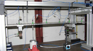
Figure 1: Engine store test rig
For the experimental identification of nonlinear structures, a resonant decay approach has been developed which improves upon previous methodologies, in particular tying in with the theoretical approach of WP3.1, and this has been demonstrated on MDOF systems with coupled modes. The strategy has the potential to be applied at industrial level as it utilises the same hardware and set-up currently used in standard GVT tests (such as the one performed in MS1) and extend it to the nonlinear regime. Here the system is excited sinusoidally close to resonance and the frequency altered slowly to ensure a resonant response. The forcing is then switched to zero and the system response becomes an unforced decay of what is approximately a nonlinear normal mode (strictly speaking a nonlinear normal mode applies to an undamped system) giving resonant decay data.
The data can be analysed to give instantaneous frequency and amplitude response components of each of the linear modes for the nonlinear normal mode. This data can be compared directly to backbone curves and reveals the nature of the coupling among linear modes due to the nonlinearity. In addition it can be used to identify the type of the nonlinearity acting in the structure and the linear modes they effect and/or couple.
The experimental backbone curve can be compared directly to theoretical backbone curves developed in WP3.1 to:
- reveal any coupling among linear modes due to the nonlinearity
- to identify the type of the nonlinearity acting in the structure
Detailed experimental tests, as part of MS1, have been completed on a structure resembling a scaled aircraft wing with discrete nonlinear pylons [3-5], shown in Figure 1, and also a joined wing half model structure containing geometric nonlinearities [1,2]. A full set of experimental data enabled an accurate identification of the underlying linear structure, natural frequencies, damping ratios and mode shapes. For the wing structure, a number of decay responses were recorded for the first four resonance frequencies. Once these responses were projected into the modal space using the matrix of mode shapes, the decaying modal responses were used to estimate the backbone curves for each resonance frequency.
The backbone curves revealed coupling between two pairs of linear modes. In addition the backbone curves showed that the structure is affected by nonlinearity that is initial softening in stiffness for small deflections followed by hardening for larger deflections. Experimental data taken from a single pylon in isolation also exhibits this softening then stiffening behaviour.
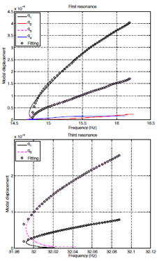
Figure 2: Experimental backbone curves
Using the experimental data, a nonlinear stiffness function that results in the experimentally measured backbone curve has been identified through data fitting [4,5]. An example of this is shown in Figure 2. The lines in Figure 2 are the experimentally identified backbone curve for an isolated resonance peak in terms of the various linear modes for the engine store structure shown in Figure 1. The circles show the equivalent curves using the fitted stiffness function. Work is ongoing to identify the behaviour of the full aircraft wing with nonlinear pylons using the experimental backbone curves, and then to apply the methodologies to the larger joined wing structure.
The third area of research is developing the process to compare the experimental data and the theoretical form to the response allowing the numerical model to be calibrated or corrected. As already stated some data fitting has been conducted on the experimental data. In addition much work has been conducted on numerical examples where we can assess the accuracy predicted model by direct comparison with the model used to generate the data set.
The method adopted is to treat the instantaneous frequency during the resonant decay along with the corresponding amplitudes of the various linear modal components at each time point as the data set. Using these along with the equations from the backbone curves taken from the numerical model, the data set can be used to identify the nonlinear coefficient values within the model, hence calibrating the nonlinear terms. This identification can be achieved using conventional least-squares fitting, but work is ongoing on investigating the use of the MCMC algorithms being developed in Theme 1 (see WP3.1).
Other ongoing work includes considering the effect of the shaker dynamics on the test structure response. It has been found that unless it is properly accounted for, the shaker’s characteristics and its location, can cause a shift in the estimated backbone curves resulting in poorer parameter identification. Compensation methods are now being developed. In addition we are now considering the fitting effectiveness when nonlinear damping and more complex stiffness relationships, including geometric nonlinearities, are present.
Furthermore, the application of the resonance decay approach using multiple shakers will be investigated and extended to nonlinear structures. This can potentially deal with systems where the underlying linear system contains close interacting modes, where current procedures fail to identify the systems correctly. Finally, with input from Rolls-Royce, under WP 3.3, a handbook has been developed to give industrial users an approach to tackling localised nonlinearities such as those seen at joints between components, delivered as MS8. These methods will be compared to the resonant decay/backbone method on the test structures considered in MS1.